
Linearization of RF Power Amplifiers: Chapter 1
Back to basics: what are modulated signals?
Understanding the basis of signal modulation and amplification

by Irene de Gruijter
November 13, 2024 in News
In this knowledge series, we delve into the challenges and solutions related to the linearization of RF power amplifiers with wide instantaneous bandwidth. A large bandwidth is a critical component in modern communication systems such as 5G networks, satellites, and radar systems. Because of this, the increasing bandwidth demands and complex modulation schemes introduce new constraints to ensure signal integrity and energy efficiency in amplifiers.
- This chapter: We begin with an introduction to modulated signals and their behavior when passing through a power amplifier.
- Second chapter: We explore the challenges posed by wide instantaneous bandwidth in RF systems.
- Third chapter: Finally, we discuss advanced linearization techniques, such as Digital Pre-Distortion (DPD), to handle bandwidths up to 600 MHz, highlighting our expertise with RFSoC platforms.
Let’s start with the basics: what is a modulated signal?
A modulated signal is a signal in which data or information is encoded by modifying certain characteristics of a base signal, known as a « carrier ». This carrier is typically a continuous sine wave, and through modulation, we change the amplitude, frequency, or phase of this carrier signal. Modulation is essential in communication systems because it allows the transmission of data over long distances by adapting the signal to the characteristics of the transmission medium.
When modulated signals pass through a power amplifier (PA), several factors come into play that affect the signal’s integrity and the amplifier’s performance. The goal of the power amplifier is to boost (amplify) the power of the incoming signal to a level suitable for transmission. However, this amplification is not always linear, which can lead to signal distortions. Understanding how modulated signals behave when going through a PA is key for designing efficient and reliable communication systems.
To make a clear differentiation, when we measure the characteristics of a power amplifier (and get the typical performances in small and large signal—S-parameters, gain, efficiency, etc.), we are sending a single signal through the PA. This is commonly named 1-tone.
When using the power amplifier in its final scenario within any communication system, it is necessary to amplify not just one, but several million signals at a time. This is why modulation is needed: modulation combines these multiple signals into a single complex waveform that can efficiently carry all the necessary information across a communication channel. This is, modulated signals « hide » encoded this large amount of individual signals into one.
When this modulated signal passes through the PA, the PA is stressed more (than if we were to make it amplify a single tone) due to its wide bandwidth and high peak-to-average power ratio (PAPR). This introduces non-linearities and distortions that affect the signal quality. Advanced linearization techniques are necessary to maintain linearity and ensure optimal performance of the communication system.
Key Concepts
Modulation Signal types
There are multiple ways to modulate signals:
- Most modern communication systems use modulation schemes like Quadrature Amplitude Modulation (QAM) and Orthogonal Frequency Division Multiplexing (OFDM). OFDM has a high peak-to-average power ratio (PAPR), while the PAPR of QAM depends on how it is implemented, especially in multi-carrier systems.
- These modulated signals carry information in both amplitude and phase. Keeping both intact during amplification is essential for accurate data transmission. The gif below (original link) gives a visual idea of this type of modulation:
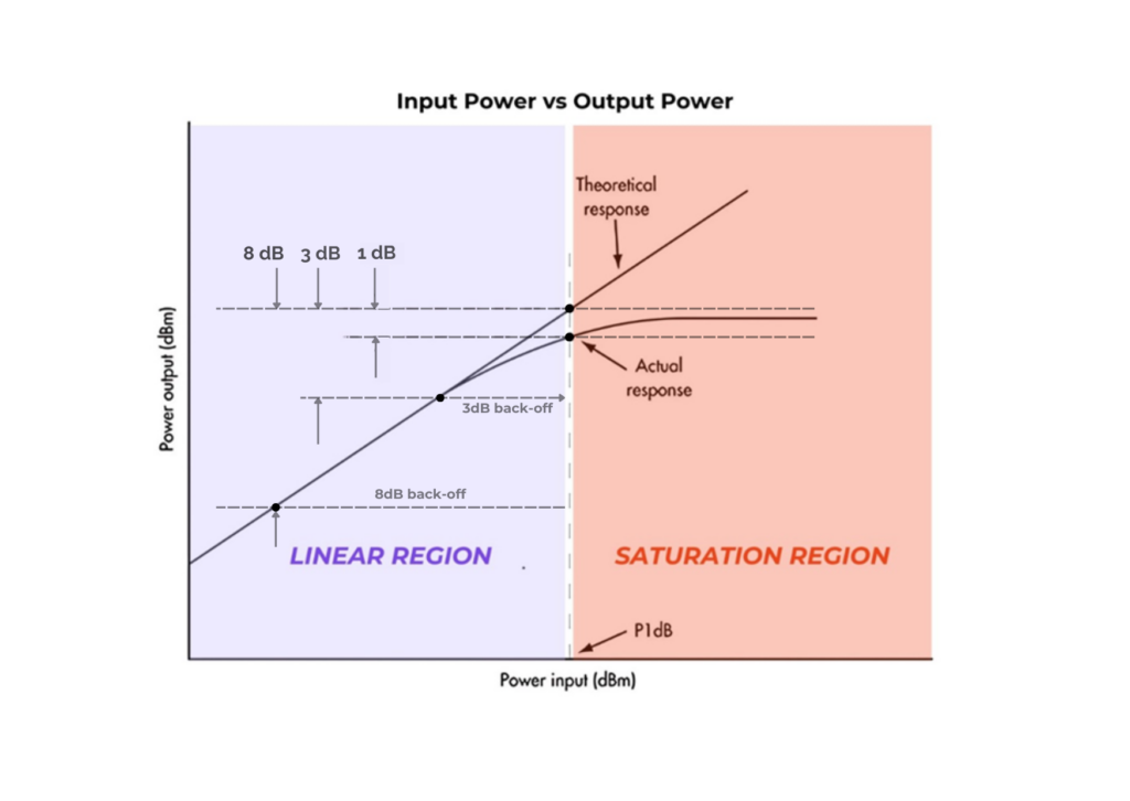
PA operating regions
When a PA is biased, it functions in different regions depending on the input power applied:
- Linear region: The PA operates linearly with little to no distortion, but efficiency is lower.
- Saturation region: The PA reaches its maximum output, where efficiency is highest, but nonlinearities become significant, causing signal distortion.
- Back-off region: PAs are operated at a power level lower than their maximum, balancing efficiency and linearity.
Linear and non-linear Amplification
When amplifying signals through a power amplifier, it is important to distinguish between linear and non-linear amplification. Linear amplification refers to the PA output being a faithful, scaled-up version of the input signal without distorting the amplitude and phase. This happens when the PA is working in the linear region.
In reality, PAs are often nonlinear, especially when driven close to their saturation point, where they are most efficient. This nonlinearity introduces distortion in the amplified signal, such as harmonic distortion and intermodulation products. These different types of distortion are relevant enough to write a whole section; nevertheless, it remains a subject under discussion that is ahead of the primary focus (signal modulation), and thus, it will be discussed in the next article (link here).
Effects of Modulation on PA Performance
Modulated signals with high PAPR are particularly challenging for PAs. One of the effects that appear after modulation is clipping. The crest factor (the ratio of the peak value of a signal to its RMS value) can cause the PA to clip the peaks if it is not designed to handle them. By clipping, we remove information from the original signal, leading to signal distortion.
As the signal’s amplitude and phase vary, the power amplifier (PA) must operate over a wide dynamic range. This makes the design more challenging, especially when high efficiency is required at lower power levels (back-off), where conventional PAs typically become less efficient.
Signal distortion types
Having mentioned the fact that distortion is going to be covered in the next article, we may as well introduce it by identifying two types of distortion:
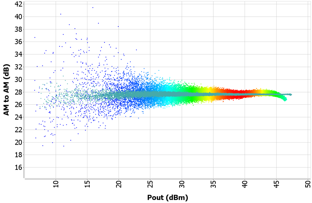
- AM-AM Distortion: This occurs when the amplitude of the output signal does not linearly track the input amplitude. This can compress or expand the signal, affecting modulation accuracy.
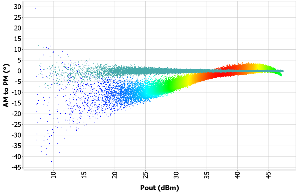
- AM-PM Distortion: Here, the amplitude modulation affects the phase of the output signal. Nonlinear phase shifts can cause significant degradation in phase-sensitive modulation schemes like QAM or PSK.
Below is an example where modulated signals pass through an RF power amplifier (PA). We can see represented in multiple colours the two types of distortion: amplitude-to-amplitude (or AM-AM) on the left and amplitude-to-phase (AM-PM) on the right. As mentioned, when different signals are amplified, they go through some level of distortion. As we increase the output level, this distortion increases. In high power levels, we can see this distortion in a way that it does not follow a straight line—it curves its way slightly downwards.
What we would logically want after obtaining this behavior is to linearize this distortion. The overlapping set of points, in grey, is the final behavior when the signals go through some linearization techniques, namely, “digital pre-distortion” (this will be covered in the next articles too). This linear, constant set of points would be the ideal behavior searched for in a PA.
Another way to look at distortion is with a spectrum analyzer. The video below shows the spectrum of a signal before and after digital pre-distortion, which is the technique used to improve the performance of amplifiers by reducing distortion that we mentioned before.
Let’s observe the red trace: it represents the signal output from an amplifier without any correction applied. Notice how the signal has high power in the center (around 400 MHz) and falls off at the edges. The blue-shaded areas represent the distortion (undesired parts of the signal) caused by the amplifier amplifying the signal in a non-linear way. The level of distortion is around -35.93 dBc on the left side and -41.16 dBc on the right side of the signal. As we increase the output power, the level of distortion increases, arriving at -31.14 dBc on the left side and -35.68 dBc on the right side of the signal.
Some techniques to manage PA behaviour:
- Back-off: In real-world systems, PAs are typically operated in a back-off mode where they provide lower output power than their maximum capacity to avoid saturation and nonlinear distortions. However, this comes at the cost of reduced efficiency.
- Digital Pre-Distortion (DPD): A common technique to counteract PA nonlinearities. DPD applies a correction to the input signal, effectively « pre-distorting » it so that the PA’s nonlinearity cancels out and the output signal remains linear.
- Envelope Tracking (ET): A technique that dynamically adjusts the PA supply voltage based on the signal envelope. This allows the PA to maintain efficiency across a wide range of input power levels without sacrificing linearity.
- Doherty Amplifiers: These amplifiers are specifically designed to improve efficiency when operating with signals with high PAPR, by combining a main and peaking amplifier that handle different parts of the power range.
Real use cases of modulated signals
Even if the use of modulated signals appears to be abstract and far from reality, here are some examples of where they are used:
- Wireless Communications:
- In cellular networks (e.g., 4G LTE, 5G NR), modulated signals like OFDM are used due to their high spectral efficiency. These signals have a high PAPR, making PA design critical to ensure efficiency and linearity.
- In practice, base stations and handsets use linearization techniques (like DPD) and amplifier architectures (like Doherty or envelope-tracking PAs) to ensure that the modulated signals are amplified with minimal distortion while maintaining high efficiency.
- Satellite Communication:
- Satellite transponders use QPSK or QAM-modulated signals, while the PA needs to operate efficiently under back-off conditions. This is mainly to avoid signal distortion, which can cause bit errors in data transmission.
- PAs used in satellites are often designed with a focus on linearity to maintain signal quality over long distances while using a limited power budget.
- Broadcasting (TV and Radio):
- Broadcast transmitters often handle AM, FM, or QAM-modulated signals. Here, linearity is important to avoid signal distortion that would affect the clarity of the broadcast.
- High-efficiency PAs with techniques like envelope tracking are often used to balance the need for high power transmission with the requirement for energy efficiency.
- Military and Radar Systems:
- Modulated signals in radar systems (e.g., pulse-modulated signals) also require PAs capable of handling rapid changes in amplitude. The linearity of the PA is crucial for ensuring accurate detection and minimizing signal distortion.

Conclusion
When modulated signals go through a PA, managing efficiency and linearity is crucial. In real-world applications, communication systems rely on techniques like Doherty amplifiers, DPD, and envelope tracking to ensure that PAs efficiently amplify signals without introducing significant distortion. These techniques are especially important in modern systems with high PAPR signals, such as 4G/5G, satellite communications, and broadcasting, where maintaining signal fidelity is critical for data accuracy and transmission quality
As we’ve explored, amplifying modulated signals in RF requires a deep understanding of both signal dynamics and amplifier behavior. In the next article, we’ll delve into the concept of instantaneous bandwidth and why it’s a crucial factor in achieving efficient and accurate signal amplification in broadband systems.
At Wupatec, our deep understanding of modulation techniques and RF amplifier behaviour ensures that our solutions are designed to maximize signal integrity and efficiency in complex communication environments.