Linearization of RF Power Amplifiers: Chapter 2
Introducing Instantaneous Bandwidth (iBW)
Discover the importance of iBW in modern communications

by Irene de Gruijter and Sullivan Plet
December 17, 2024 in Knowledge Center
This knowledge series delves into the challenges and solutions related to linearising RF power amplifiers with wide instantaneous bandwidth. A large bandwidth is essential for modern communication systems, with 5G networks being the most notable example today. Because of this, the increasing bandwidth demands and complex modulation schemes introduce new constraints to ensure signal integrity and energy efficiency in amplifiers.
- First chapter: We introduce modulated signals and their behaviour when passing through a power amplifier.
- In this chapter, we explore the challenges of wide instantaneous bandwidth in RF systems.
- Third chapter: Finally, we discuss advanced linearization techniques, such as Digital Pre-Distortion (DPD), to handle bandwidths up to 600 MHz, highlighting our expertise with RFSoC platforms.
What is instantaneous bandwidth?
Let’s take it from the beginning. In RF systems, and from the RF PA design point of view, the term « bandwidth » typically refers to the range of frequencies an amplifier can work with. For example, a power amplifier might be designed to operate across a frequency range of 3.4 to 3.8 GHz. This means its RF bandwidth would be 400 MHz, and it can amplify a single signal (1 tone) at 3.4 GHz, 3.6 GHz, 3.8 GHz, or anywhere in between.
The term instantaneous bandwidth (or iBW) is slightly different. Mathematically, it refers to the range of frequencies that an RF power amplifier can amplify simultaneously. But what do we mean by this?
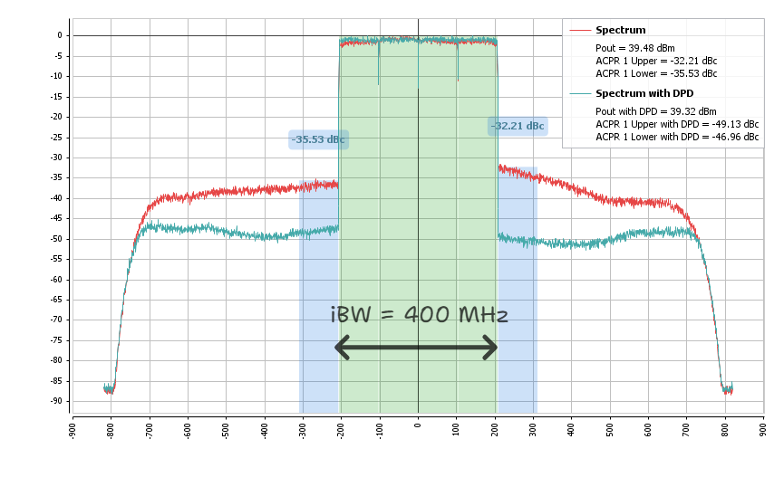
Technically speaking, iBW defines the width of the signal spectrum that the amplifier can amplify at any given time. In practical terms, it’s the ability to amplify a modulated signal (see previous article on modulated signals) that covers a certain frequency range—for example, modulated signals with 400 MHz bandwidth. To better visualize it, consider the spectrum below, which shows four 100 MHz adjacent channels with a total IBW of 400 MHz.
This distinction is important. A power amplifier may operate within a specific RF bandwidth (for instance, from 3.4 to 3.8 GHz, which equals a 400 MHz RF bandwidth). However, if its instantaneous bandwidth (iBW) is too narrow—say 200 MHz—it will have difficulty amplifying signals that use a wider frequency range. This limitation can lead to signal distortion, potentially causing the amplifier to fail to meet established standards. The European Telecommunications Standards Institute (ETSI) sets standards within 5G New Radio (NR) of “how much distortion can be accepted ». Speaking more technically, they ensure compliance with regulatory and interoperability requirements (an amplifier can create distortion, but as long as it stays within the limitations of its final application AND ETSI’s maximum requirements, it’s okay!).
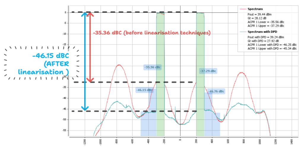
One example of observing distortion is measuring ACLR levels. ACLR (Adjacent Channel Leakage Ratio) measures the leakage of transmitted power from a carrier signal into adjacent frequency channels. It is a parameter that ensures that a transmitter does not interfere with other users or services operating in adjacent frequency bands. It is not the only parameter that measures distortion; there are others, like error vector magnitude (EVM), that will be covered afterwards. Later in this article, we will discuss ACPR (Adjacent Channel Power Ratio), which is similar to ACLR but often more flexible in terms of the adjacent channel definition and used for measuring amplifier performance (and more in line with this article’s topic). In any case, both terms are used interchangeably to represent the same thing. To give an idea of what ACPR/ACLR looks like, in Figure 1, we can see ACPR levels before and after the amplifier is linearised. The red trace represents the amplifier performances before linearization, and in green/blue, after it is linearised. Before linearisation, ACPR levels are from -35.2 to -35.5 dBc, and after, -46 to -49 dBc (indicated on the upper right legend).
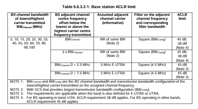
If we were to apply current European Standards to our amplifier, we would use ETSI TS 138 104 V17.8.0 (2023-01), page 67. Before linearisation (the red trace), our amplifier would not be accepted (it has -35 dBc and the norm states that the limit is -45 dB). However, after linearisation, our amplifier will comply with the norm and be ready for use.
The role of Digital Pre-Distortion (DPD)
One of the techniques that allows to maximize linearity while maintaining signal fidelity is digital pre-distortion (DPD). In theory, increasing iBW means amplifying a wider range of frequencies simultaneously. This can introduce distortions because most power amplifiers are inherently non-linear devices. These usually appear in the form of high ACPR levels, that result in unwanted interferences with neighbouring communications systems and potentially violate regulatory limits in some RF environments. For instance, if we take the example above (Figure 1), we can see that ACPR levels before the DPD is applied are -32.21 dBc and -35.53 dBc (not acceptable according to today’s standards!). When the DPD is applied, the ACPR levels reach -49.13 dBc and -46.96 dBc, making the PA suitable for any modern communication system. With these values, we ensure that the interference is reduced and we meet modern communication requirements.
DPD helps to overcome the linearity challenge. It works by pre-distorting the input signal in such a way that the amplifier’s non-linear behaviour is compensated for. In essence, DPD counteracts the distortions introduced by the amplifier, allowing the amplifier to process wideband signals more linearly. This results in improved performance across the iBW, reducing EVM, ACPR levels and gaining linearity.
By combining different algorithms, such as DPD, with our amplifier designs, we enable high-performance amplification of wideband signals, ensuring they are transmitted with minimal distortion. This is a key part of Wupatec’s value proposition—not just amplifying signals, but doing so with a high degree of fidelity and efficiency.
How we optimise and measure instantaneous bandwidth
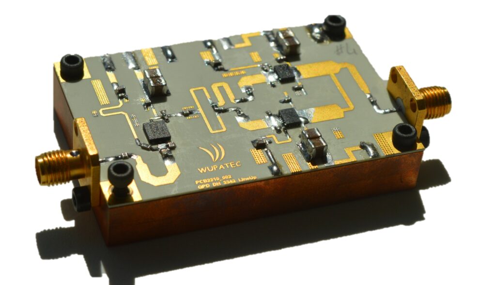
At Wupatec, we design RF power amplifiers with a focus on finding the best balance between iBW and efficiency. Our amplifiers are not only capable of covering broad RF bands but are also engineered to provide wide instantaneous bandwidths, ensuring that they can amplify wideband signals without degradation.
This is especially important in industries like New Space, where satellite payloads require RF amplifiers that can handle varying signal conditions. As more complex and high-data-rate communication systems are deployed, the need for amplifiers that offer sufficient iBW becomes critical.
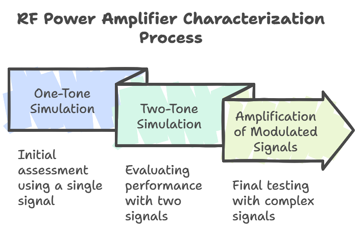
To have a better idea of how our RF Power Amplifier (RF PA) would respond undergoing modulated signals, we can start with simple simulations during the design phase that subsequent measurements will validate.
1-Tone Simulations
When we characterise an RF PA to obtain the main figures of S-parameters, power gain, efficiency, etc., we send a single sinusoid; we usually refer to this as one-tone (simulations/measurements).
This gives an overview of the RF PA’s behaviour, but it is not enough if we want to see the amplifier’s behaviour in its final use case: amplifying modulated signals.
2-Tone Simulations
The next step would be to carry out a 2-tone simulation, where two sine waves, centered at two different frequencies, f1 and f2, are sent to the RF PA to be amplified. These signals are separated by Δf (in some books named “carrier spacing”). Through this kind of simulation, we get closer to the behaviour of the PA when amplifying modulated signals, which would be the last step of the process.
There are two main things to analyse in a two-tone simulation:
- The amplifier’s intrinsic linearity at the desired output power (measured in dBc)
- An estimation of the amplifier’s instantaneous bandwidth (through IMD3 asymmetries).
Whenever we send two tones to an amplifier, apart from amplifying the original signals at f1 and f2, the amplifier will create nonlinear effects like intermodulation distortion (IMD), harmonics, and other types of distortion. This is because the amplifier has a non-linear transfer function and is used in its non-linear region for delivering efficiency. These phenomena degrade signal quality and can create interference in adjacent frequency bands. As we can expect, as Δf increases, distortion becomes more pronounced and asymmetrical. Symmetric distortions can be corrected – linearised – through algorithms such as DPD. However, when distortions become asymmetric, the situation changes significantly. This can be seen when we plot IMD vs. Δf. In Figures 4 and 5, we have both 3rd-order intermodulation products, IMD3 high and IMD3 low. The larger the carrier spacing, the more pronounced the intermodulation products and asymmetry become.
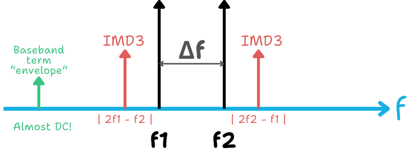
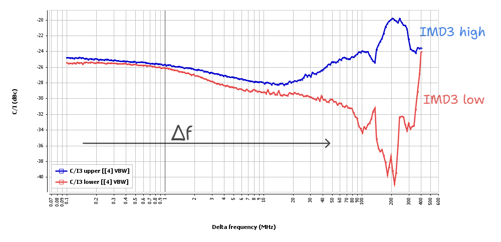
There is another baseband term that appears as we augment Δf (Figure 4, represented in green). It is important to the point that it can change the behaviour of the transistor’s gate voltage, impacting the amplifier’s overall behaviour. This term appears at very low frequencies (DC) and is commonly known as the envelope. Again, the bigger the Δf, the more important this effect becomes.
These statements highlight the challenge of augmenting Δf while avoiding unwanted behaviours. (Larger Δf indicates augmented iBW). Various studies cover this (undeniably relevant) subject as it tackles the growing demands of mobile communications that require larger and larger iBWs. However, we will leave it for another article as it deserves a dedicated discussion.
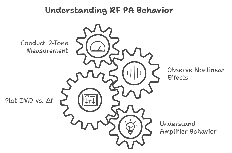
Through these simulations, we have a larger image of the “real” bandwidth (iBW) of our power amplifier when modulated signals go through it. Sometimes, we design RF PAs that cover an RF bandwidth of 900 MHz and validate it during the simulation phase (through a 1-tone simulation). With a 2-tone simulation, we can get an idea of its iBW. It is when applying modulated signals that we measure an iBW of 600 MHz with the required linearity specifications of the target application.
Measuring modulated signals and determining the instantaneous bandwidth
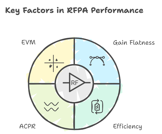
The final step in the process, after having done 1 and 2 tone simulations (and consequent measurement), is to measure the RFPA while passing through modulated signals. Here, we obtain the final behaviour of our RFPA amplifying these signals, covering the desired bandwidth. To see the iBW of the RFPA, we need to analyze its frequency response and determine the range of frequencies over which the PA operates without distortion. For this, we connect a spectrum analyzer to the output of the PA (with appropriate attenuation) and pay attention to four key metrics: gain flatness, efficiency, ACPR (adjacent channel power ratio) levels, and EVM (error vector magnitude). Let’s introduce these terms:
Briefly explained, gain flatness refers to how consistently the PA amplifies all frequencies within the signal’s bandwidth. Ideally, the output should have a uniform amplitude gain across the entire frequency range of the signal (excessive variation leads to distortion or signal degradation at certain frequencies).
Efficiency in an RFPA measures how it converts DC power into RF output power, expressed as a percentage. High efficiency minimizes power loss and heat, ensuring reliable operation across the iBW.
The third parameter, ACPR, measures the amount of signal power « leaking » into adjacent frequency channels outside the intended bandwidth. It is relevant because high leakage can cause interference with signals at neighbouring frequencies (where another communication system may be transmitting, for example). We can see the power levels of the adjacent channels in the spectrum and calculate the ratio between the transmitting and neighbouring channels.
EVM measures how accurately the PA reproduces the modulated signal by comparing, after demodulation, the phase and amplitude of the transmitted signal to the ideal reference signal. A high EVM indicates that the PA introduces distortion, which degrades signal quality and disturbs the decoding part at the receiving end. The lower the EVM, the better the PA will perform.
The importance of iBW
Signals in many RF applications, including telecommunications and satellite communications, are becoming increasingly complex and require modulation. Instead of simple « tones » or narrowband signals (small IBW), RF systems are often tasked with amplifying wideband signals—modulated signals that span hundreds of MHz. Suppose the RF bandwidth of a power amplifier is too narrow compared to the bandwidth of the modulated signal (aka iBW). In that case, the amplifier will distort this signal, leading to degraded system performance.
For example, in 5G telecommunications or satellite systems, signals can easily occupy hundreds of MHz of bandwidth. If the amplifier’s IBW is insufficient, it cannot faithfully reproduce these signals, resulting in a loss of data integrity or increased error rates. This makes IBW an essential factor in the design and performance of modern RF systems.
Example
Suppose your PA covers the frequency of 3.3 GHz to 4.2 GHz (thus, an RF bandwidth of 900 MHz) and amplifies a 64-QAM signal with a bandwidth of 600 MHz (iBW). Here’s how these metrics may be applied:
- Gain Flatness: no part of the 600 MHz bandwidth should have lower or higher amplification than expected; this means that gain variations must stay within an acceptable range (e.g., +/-0.5 dB).
- Efficiency: During the PA’s design, building a matching network that allows the transistor to deliver maximum efficiency over a wide bandwidth is a challenge.
- ACPR: the adjacent channels (e.g., at the left and right sides of each 100 MHz channel) should have sufficiently low power to avoid interference (for instance, around -45 dBc according to today’s standards). We can see in the spectrum trace in Figure 9 that before DPD, the ACPR levels reach -35.36 dBc, and this is improved once the DPD is applied, reaching -46.15 dBc.
4. EVM: the modulated constellation points should be close to their ideal positions, ensuring the signal’s integrity (Figure 10).
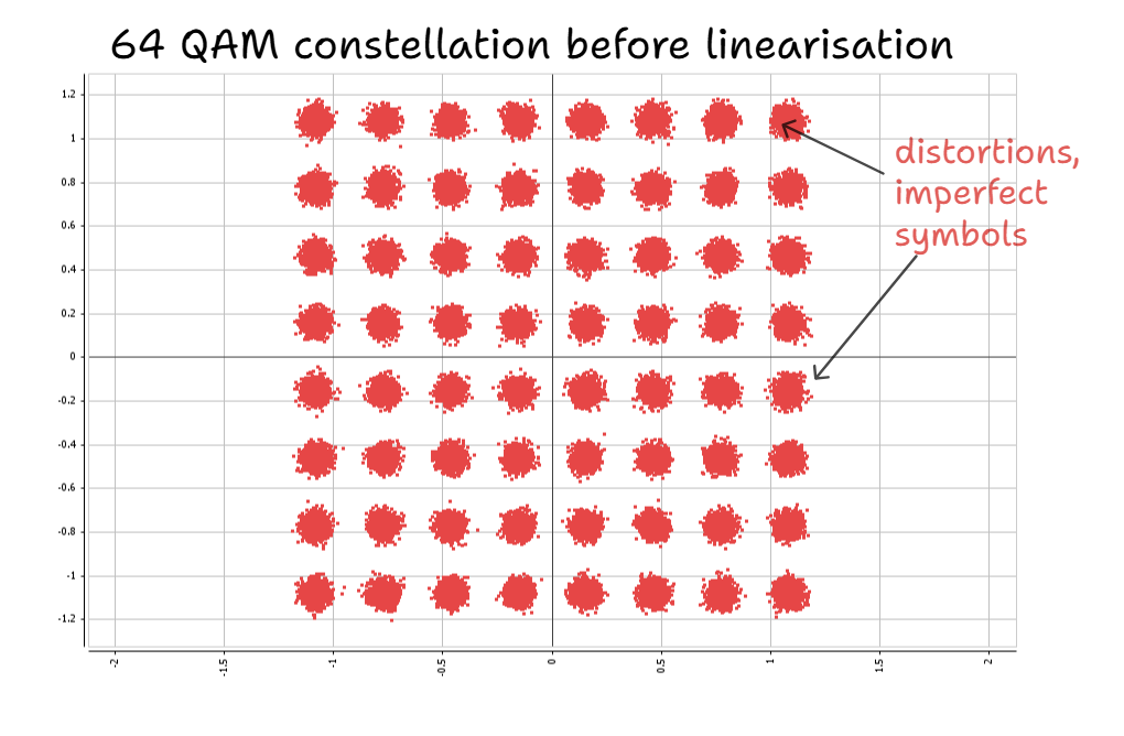
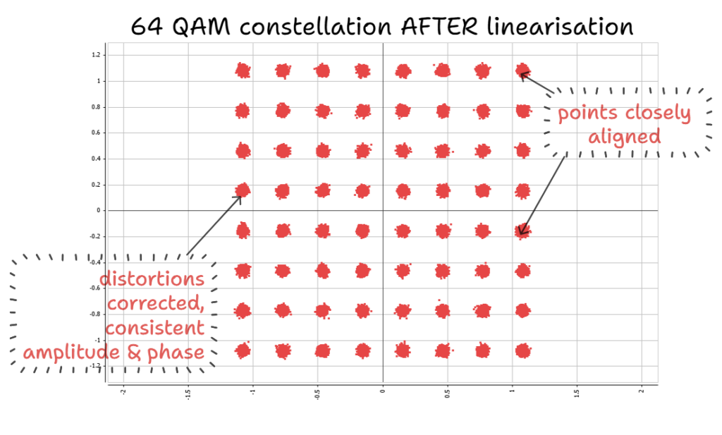
Fig. 10. A 64 QAM constellation before and after linearisation (DPD in this case). To represent it, we used IQSTAR.
Wupatec’s amplifiers — Built for the future of RF communications
The importance of instantaneous bandwidth in RF power amplifiers cannot be underestimated, particularly as the world moves towards more advanced communication systems with increasingly wideband signals. At Wupatec, our expertise in designing amplifiers with a focus on both instantaneous bandwidth and linearity ensures that our products meet the needs of modern RF systems.
Wupatec power amplifiers are designed to handle the challenges of wideband signals, offering flexibility, efficiency, and scalability whether you are building systems for terrestrial communications or space applications. As the demand for wider bandwidths grows (especially in the new openings in the FR3 band), our amplifiers are ready to deliver the performance your system needs.
Stay tuned for the next article, where we will discuss DPD and other linearization techniques more in-depth. We will also discuss how we arrive at linearizing iBWs of 600 MHz thanks to our expertise in combining RF PA design with the RFSoC.
References:
European Telecommunications Standards Institute. (2023). 5G; NR; Base Station (BS) radio transmission and reception (3GPP TS 38.104 version 17.8.0 Release 17). ETSI. Retrieved from http://www.etsi.org/standards-search


