During the summer, Wupatec has been working on the ALMA Project (Atacama Large Millimeter/submillimeter Array).
ALMA is today the most powerful radio telescope of its kind. It consists of 66 antennas installed at an altitude of 5,000 meters on the Chajnantor Plateau, in Chile’s Atacama Desert, one of the driest and most stable locations on Earth for observing the sky at millimeter and submillimeter wavelengths.
Unlike an optical telescope, ALMA does not “see” visible light. Instead, it detects radio waves from ~30 GHz up to nearly 1 THz, enabling scientists to study phenomena that are otherwise invisible, such as:
-
extremely cold molecular clouds only a few degrees above absolute zero,
-
the formation of stars and planetary systems,
-
very distant galaxies whose light comes from the early universe.
Through interferometry, the antennas function collectively as a single high-resolution system, with all signals processed in a central correlator to deliver very precise images and spectral data.
ALMA is an international collaboration between ESO (European Southern Observatory), NSF (National Science Foundation, United States), and NINS (National Institute of Natural Sciences of Japan), in partnership with Chile. Its infrastructure, including its RF reception chain and cryogenic receiver systems, requires a very high level of engineering in both radiofrequency and digital domains.
We suggest having a look at their official website, where all this information is explained in a short movie, and every discovery is shared: https://www.almaobservatory.org/en/about-alma/
The task
WUPATEC and AMCAD teamed up to support the design and simulation of key elements of the intermediate-frequency (IF) receiver chain. This chain, which is part of the signal path that begins in outer space, is captured by the antennas and travels all the way to the analog-to-digital conversion stage.
Inside a cryostat, the receivers down-convert sky frequencies ranging from 30 GHz to nearly 1 THz into an IF band between 0 and 20 GHz. These signals, at millimetric and sub-millimetric wavelengths, originate from extremely cold molecular clouds and from some of the earliest and most distant galaxies ever observed, making the performance of the IF chain absolutely critical.
As part of the ALMA program, we are grateful to the Laboratoire d’Astrophysique de Bordeaux (LAB, Université de Bordeaux) for their trust and collaboration throughout the project.
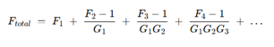
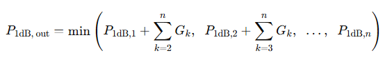
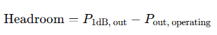
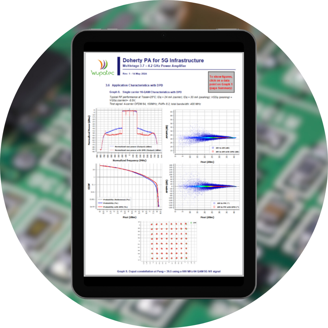
In this joint effort, AMCAD and Wupatec delivered a tailored anti-aliasing filter and carried out a full analysis of the signal path: overall gain, noise figure, compression, ripple, and complete frequency-response simulations of the IF chain, including cables, connectors, and PCB layout effects. They also proposed optimizations to ensure performance stayed aligned with the project’s tight requirements and consolidated everything into a detailed final report presenting the optimized architecture and the associated simulation results.